Meanwhile, don't click here. :)
Tuesday, October 18, 2011
What's New?
I have some new layouts to be posted, like from Okko's and Wampler TW. I apologize for those who asked for layouts thru email, sorry I just can't do that. I'm trying to find another free sharing site to post them there. And besides, I'm very busy right now.
Tuesday, January 25, 2011
Thursday, January 6, 2011
ToneFreak Severe Distortion

Basically, a Marshall Guvnor derivative distortion pedal which is more similar of that from MI Audio's Crunchbox. Clipping is at the feedback loop of the opamp rather than shunting it to ground as seen in the latter.
A few notes:
- the VOLUME pot's Wiper(2) is the effect OUT.
- An SPDT with CENTER OFF toggle switch is used(this is much of a PRESENCE function similar to Crunchbox, only with a fixed 4.7K resistor). "center" pad refers to the CENTER pole of the toggle switch.
- CLIPPING selector switch, use an SPDT with CENTER OFF toggle switch same as mentioned above. Pads located between the 51pF cap and 10K resistor just above the opamp.
- Si refers to Silicon diode(i.e. 1N4148 or similar)
- Ge refers to Germanium diode(i.e. 1N34A, 1N60, etc)
- All SQUARE pads of the diode is the CATHODE.
- The 1M resistor beside the JUMPER, the 100pF and 2.2uF cap is actually 560K in actual SEVERE units.
- Leave the pads empty labeled as "LED" just above the 1N4001 protection diode.
There you have it!. Rawk on!.
Layout Download
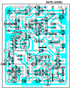
MXR Micro Chorus MN3007 retrofit

This has been discussed at the stompbox forum. First, This is NOT yet verified as far as I'm concerned. I haven't built one either since I have my CE-2 clone. The layout is only based from the retrofit's schematic using MN3007 BBD instead of the original SAD512. Suppose, if the retrofit schematic is correct and working, then there is no reason that the layout won't work. By then, build at your own risk!. Pot is 500K reverse log(audio) type. Transistors could be any common NPN's (2N5088, 2N3904, etc).
(PS: May mga follower na din pala ako na taga.PM..pagkakuyaw jud mga bai!..)
Layout Download
Tuesday, September 21, 2010
Echo Base Digital Delay

This is my version of Ian's(slacker at DIYstompboxes.com) Echo Base PT2399 digital delay with minor alterations. I use JFET switching instead of 4066 CMOS switching. Some time ago I had problems with this CMOS leading my unit to fail and I don't even know why. Haha. Anyway, pot values are; LEVEL, REPEAT, and DEPTH is 100K-audio(you might want to try linear tapered pots on these); TIME is 50K linear taper; and SPEED is 1M linear( but I used reverse log taper on my build, so you decide!).
I use J113 for the JFET's salvaged from an old broken DOD pedal. You can use either J201 or similar. And also I used an 11 volt zener(1N4741) as protection diode. Bypass switching is illustrated in the pdf file.
The layout is very compact, designed to accomodate miniature electrolytics or boxed film capacitors. Layout's verified? Oh yes!
Layout Download
Labels:
delay,
digital delay,
echo base,
modulation,
Princeton,
PT2399
Subscribe to:
Comments (Atom)


